1.1.1 - Architecture of the CPU
In this section we cover the very low level fundamentals of a computer. By the end you should understand what a computer is, what it is and is not capable of doing and why the CPU is central to all that happens inside any computing device.
In this section (click to jump):
- The Definition of a Computer
- The CPU
- The Fetch Decode Execute Cycle
- CPU Instructions - Operator and Operand
- Components of a CPU
- A Detailed Fetch, Decode, Execute Cycle
The Definition of a Computer
A computer is:
- A machine...
- Which takes data in the form of numbers (binary numbers) as input
- Performs calculations on them
- Provides output (the answers)
- and does this repeatedly until you tell it to stop or turn it off.
As you will find out later on in the course, the only thing a computer is capable of doing is applying fixed logical rules to binary numbers. How, then, is it possible to create incredible visuals like the latest Playstation game? What about your favourite music that you just streamed - that can't be numbers, can it?
Your computer is plugged in to the mains, or powered by a battery. This means it runs on electricity. Nothing crazy so far, right?
Computers need to be absurdly reliable and work all day, every day without missing a beat. To achieve reliability with electricity we need to be able to control it in an extremely predictable way. It turns out, there is only one way to sensibly do this - use switches to turn the power on and off.

This is where, for some people, computing gets so bonkers their eyes glaze over and a slightly bemused expression takes hold.
The idea that you can make a YouTube video happen by wiring up a few billion switches is just too much - yet it is exactly what is happening inside all computers, all phones, all tablets... any device with a microchip inside it.
In theory, you could wire up many thousands of light switches to create circuits just like the ones inside a computer. Only this would be slow, manual and frankly a waste of the rest of your entire life.
Switches, as you may have noticed, have two options - on or off. There is no ambiguity, no half way, the switch is either on (allowing current to flow) or off (completely breaking the circuit so there is no flow). We then translate the state of a switch in to numbers - ON = 1 and OFF = 0.
This is why computers are forced to use a binary number system (bi meaning "of two") as everything must be represented as a switch being either off or on, giving only two possibilities for each switch state. The switches inside a circuit are made up of unimaginably tiny switches called transistors. These are so small you could easily fit several hundred thousand on a single human hair.

Transistors are arranged and connected together to form something called "logic gates" which are simple circuits that will manipulate a binary number based on a set of even simpler rules. This is based on the work of George Boole, a mathematician from the 1800's who was obsessed with the idea that there was a "truth" for any given situation. In other words, he believed any problem could be described using numbers and solved using maths. I bet he was stunningly interesting at parties...
In order for a computer to do anything useful, we have to convert absolutely everything from real world form into binary numbers. When you speak to Siri, your voice is being captured by a microphone, converted into an electrical signal which is then sent to an "analogue to digital converter" which then translates the signal into a stream of binary numbers. It is then up to beardy computer programmers to write code which will take that data stream, make sense of it, and get the computer to do something useful with it.
You will learn more about how we turn the real world in to binary later in the course, but this should be enough of an introduction for now that you at least understand the scale of the problem that has been solved by computer scientists over many decades, and also what on earth is really going on inside your devices.
The CPU
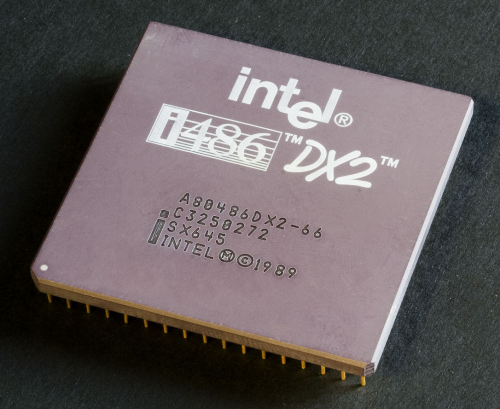
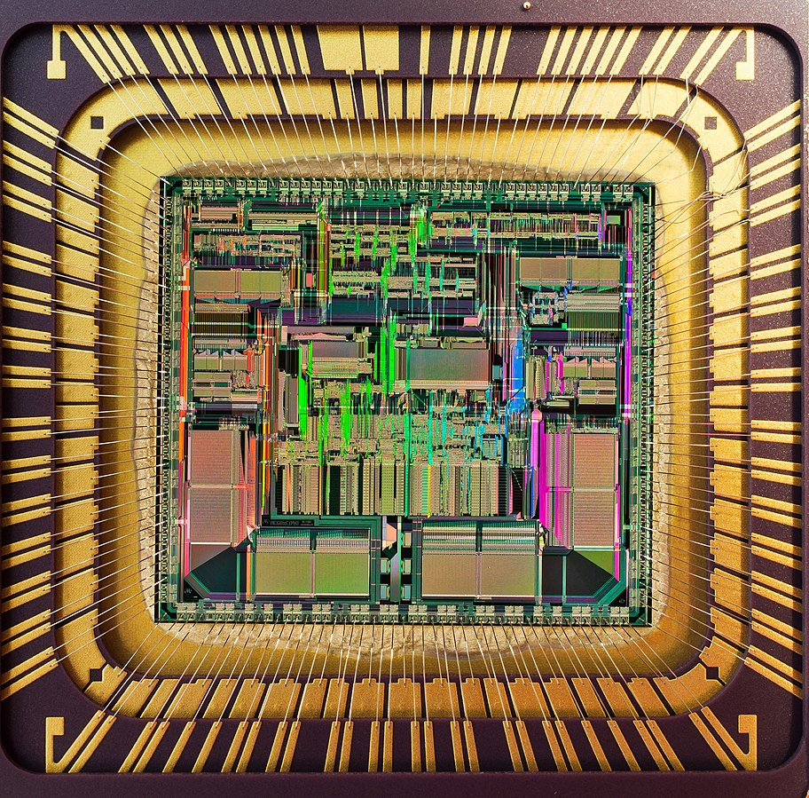
The CPU is the most important component in any computer system and an absurdly complex piece of circuitry.
To understand how a CPU works it is important to recall the following key points
- Computers are electronic devices. They control the flow of electricity using switches called transistors.
- A transistor (switch) can only be in one of two states - on or off. This is represented as the numbers 1 or 0, commonly known as the binary number system.
- Any computer, therefore, can only understand information which has been translated into a series of binary numbers.
- A computer works by following lists of instructions called programs (or software, or applications)
- The instructions we can use in a program are fixed and are called the "instruction set."
Instruction Sets
Let's look at instruction sets in more detail.
Imagine a TV remote control. There are a set number of buttons on there, each one corresponds to a function of your TV. Unless you change your TV for a new one, these buttons and functions will never change. Think about it - your TV doesn't suddenly gain new abilities from one day to the next.

You can think of your TV remote as the "instruction set" of your TV. Everything it can do is on a button somewhere on that controller. By pressing these buttons, or in some cases combinations of these buttons, you can get the TV to do what you want such as schedule the recording of your favourite show.
A CPU is no different, it has a very simple fixed set of instructions that it is capable of carrying out when requested by a computer program. In a great simplification of the truth, you can imagine that each instruction requires its own special circuit. These circuits are all placed together in the CPU and once it leaves the factory, it is impossible to add new instructions at a later date - they are literally and physically fixed in place!
Although a CPU is a wildly complex piece of engineering, because it is operating at such a low level (meaning it operates solely on binary numbers represented by switches) the instructions it can carry out are all very simple in nature.
For example, most CPU's will have instructions such as:
- ADD - add two numbers together
- COMPARE - check if one number equals another
- JUMP - get the next instruction to carry out from another place
- MOVE - literally move a number from one place to another in memory
These are not very complicated operations at all, are they? In fact most CPU instructions simply involve moving a piece of data (a number) from one place to another, making a decision based on a calculation or manipulating a number by moving it around. Because of the simplicity of each instruction it takes many, many instructions to do anything remotely useful. Just moving your mouse across the screen requires hundreds of these instructions being carried out.
This explains many of the following things:
- Programs are really, really long - because we need lots of simple instructions to do something complex
- We have invented "high level" languages (ones that look like English rather than gibberish) because programming using binary CPU instructions or mnemonics (called assembly language) can be very complex.
- CPU's must be very, very fast at carrying out these instructions simply because it takes many hundreds or even thousands of instructions to do anything that we would consider useful.
To summarise and conclude our learning so far, we can say that a CPU is:
- A piece of hardware called the Central Processing Unit
- The place where all program instructions are carried out (we say they are "executed")
- Capable only of doing a set number of things (the instruction set)
So it's the piece of hardware in a computer system that makes things happen! Without it, you couldn't run any programs. Indeed, you couldn't even turn the machine on.
The Fetch Decode Execute Cycle
Not one for words and reading? Worried you'll run the batteries out for your eyes? Don't worry, there's a video for this bit!
By this point we know what the CPU is and what it does:
- It is the Central Processing Unit
- A CPU only understands binary numbers and instructions that are "encoded" in binary
- When told to, it gets program instructions one by one
- The CPU carries these instructions out - executes them.
But the next step in our understanding is to work out exactly how it does this.
The CPU carrying out a program or executing a series of instructions is known as processing. Processing happens in a cycle. From the moment you turn your computer on until you turn it off, the CPU is literally doing nothing but going round and round processing instructions. Even when you leave your computer alone and it appears to be doing absolutely nothing, the CPU is still processing instructions - it doesn't know any other way. It's like a workaholic that never takes a break, never stops working and never has a breakdown, turning itself into a gibbering wreck.
You've been doing cycles since you were in reception class - life cycles, the water cycle, the art of balancing on a unicycle whilst juggling flaming badgers. All standard stuff. So here's another cycle for you and it's called the Fetch, Decode, Execute Cycle:
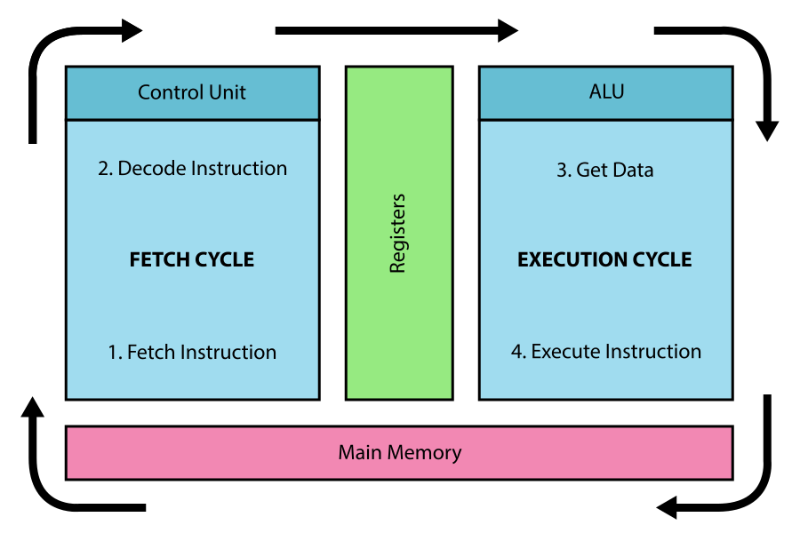
The CPU is doing 4 things repeatedly, over and over again, to make the programs we give it work.
Let's break these steps of the cycle down into their component parts:
1. Fetch:
- Programs (instructions and data) are stored in memory (RAM - you'll learn about this later, for now it is a place where data is put whilst we use it)
- The CPU FETCHES an instruction from memory. This is really important - in an exam people often make the mistake of saying that instructions are sent to the CPU, they're not, the CPU requests them when it needs them from RAM.
2. Decode:
- The CPU then has to work out what the instruction means. It literally asks "what have you asked me to do?" If it makes life better, imagine the little computer people sat there with a big book, like a dictionary, and every time an instruction comes along they look it up in the book and read out the meaning so the CPU understands.
Believe it or not, the CPU has to work out what an instruction means every single time. You could ask it to do the same thing 1000 times in a row and it would look it up 1000 times. Remember a CPU is not intelligent and cannot "think" for itself. - Once the CPU has decoded the instruction it fetches any additional data it may need and "sets up" the CPU ready to carry out the instruction.
3. Execute:
- The CPU now does what you've asked it to, it carries out the instruction. Add a number, jump to another program instruction or compare two pieces of information, for example. The CPU will pass the data through the correct circuit to actually carry the instruction out.
Usually these instructions are carried out in somewhere called the Arithmetic and Logic Unit (ALU) because, you know, most instructions are either maths or logic. Innit. - This processing is usually carried out in something called a "register." More on those later (keep reading, it's got more cliff hangers than Hollyoaks this...(but far less murders and deaths than is apparently normal for a small Cheshire village))
4. Store:
It'd be a bit weird if after doing an instruction the answer didn't go anywhere, or we just binned it. So the final part of the cycle is to put the answer somewhere. This can either be:
- In a register (a piece of memory in the CPU) ready for further use by another instruction
- Back in main memory (RAM) so it can be used later.
CPU Instructions - Operator and Operand
We discovered earlier that the CPU carries out very simple instructions extremely quickly. You should also be aware that CPU instructions don't do a great deal, perhaps store a number somewhere or compare two numbers.
These instructions are stored in RAM (the computers memory) and are fetched when the CPU needs them. Memory is organised into millions of tiny spaces, each of which can store a single instruction or piece of data. To find these spaces they are given a unique address, just like your house. As a consequence of programs and data being placed in memory, the CPU usually needs to know where to find instructions and data, meaning each instruction is usually followed by an address as follows:

In the example above you can clearly see that we have an instruction "ADD" followed by some information. Forget the symbols for now, what we are interested in is the number, in this case 01. Without this extra data, how would the CPU know how much you wanted to add to another number?
Here's another example:

Again, you can see that two part structure. This time we are using the instruction "compare" meaning "is this the same as something else?" This is followed by a the number 8010 - a memory address holding the data we are going to compare.
These two distinct parts of a CPU instruction have names that we need to know about for the exam - Operator and Operand. It's definition time:
Operator - This is the instruction, the thing we want the CPU to actually do. In the examples above we want the CPU to add two numbers or compare two numbers.
Operand - data which identifies where or how the instruction should be carried out. It is nearly always a number or a memory address.
Luckily at GCSE we don't need to worry about whether the number is a memory address or just literally a number.
In summary, then, what do you need to know for the exam:
- The operator is the first part of the instruction and tells the CPU what to do.
- The operand is the memory address or data that is needed to tell the CPU how to use that instruction.
Components of a CPU
I keep talking about these things called "registers" and the "accumulator" like you actually know what they are. It's time we solve the mystery and clarify what is actually inside a CPU and what makes it tick (quite literally tick).
Here's a fascinating diagram of the inside of a CPU:
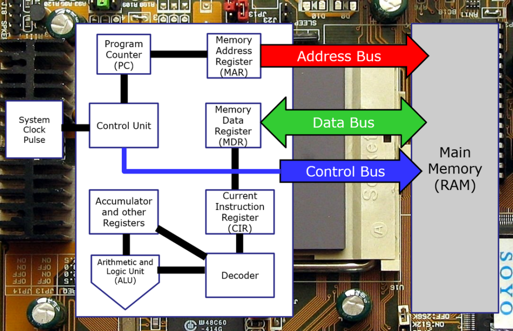
Everything inside the large white box is inside the CPU. We've introduced quite a few ideas and concepts in this diagram so the next few sections will go through these in detail.
Registers
When a CPU fetches an instruction from memory it "registers" (stores) it inside a tiny piece of memory called... a register.
To clarify, memory is a piece of computer circuitry which can hold a set of binary numbers (0 or 1) until it is needed at a later point. Each 0 or 1 is called a bit of data and usually a single memory location or register can hold a set of 8 bits. Modern memory has millions of these locations to store data.
As a CPU only deals with single instructions and single pieces of data at any one time, a register will hold one piece of data that is 32, 64 or in some cases even 128 bits wide. Whether this is an instruction or a piece of data will depend on the purpose of the register. A register may have a special purpose, such as holding status information or for working with specific parts of the CPU or they may be general purpose.
In your exam you will be expected to know the name and function of the following generic registers:
- Accumulator - a general purpose work and data storage register
- Memory Address Register - the address of the location in memory we want to read or write to
- Memory Data Register - the data we read from memory or want to write to memory
- Current Instruction Register - the instruction we are working on right now
- Program Counter - the address of the next instruction to be executed
The Clock
A quick detour is necessary to discuss the system clock.
Computers rely heavily on perfect timing - everything must happen in an entirely predictable manner, at just the right moment for a variety of reasons. To make this happen all computers contain a clock, but not like the one you'd find on the wall.
The system clock in modern computers is usually a crystal oscillator chip, which is a posh way of saying it is a chip which produces an extremely accurate, predictable electrical signal (called a clock pulse) at a specified speed. It will usually generate many millions of pulses per second.
The CPU is controlled by this system clock, without it the CPU would have no sensible way of knowing when to perform the next operation, or be able to time critical events such as reading in data. Put simply, the clock is the beating heart of any computer system, when the system clock "ticks" the CPU knows to perform the next part of the fetch, decode, execute cycle.
Program Counter
The Program Counter or PC is essential to the running of any program. It is a register that simply contains a memory address, but its role is absolutely crucial to the control of the whole system.
How does a CPU know which program to run? How do you switch from one program to another? How does it know what to do next? The answer to all these questions is the Program Counter.
If you remember back, you'll know that a program that we want to run has to be placed into memory. This means that there are thousands of instructions and pieces of data all placed neatly into memory locatons so the CPU can access them. In order to run the program, we simply place the memory address of where the program begins into the Program Counter. The CPU will then begin executing these instructions immediately on the start of the next cycle. The CPU then updates the value in the Program Counter itself so it can move on to the next instruction in the program.
To be clear, we say that the Program Counter holds the memory address of where the next instruction to be executed is in memory.
To recap our understanding of CPU components so far, we have learned that:
- There is a system clock which controls when things happen in the CPU
- There is a Program Counter, which is a register holding the address of the next instruction to be carried out. This means the CPU knows what to do next and can also be changed to switch the program we are currently running to another.
The Accumulator
The accumulator is a register. It is usually used to hold the piece of data the CPU is currently working on or the result of the last instruction that was carried out. The accumulator is the most commonly used register in many processors.
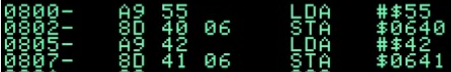
To put this in context, imagine we want our program to take the number 5 and add 3 to it. To make the CPU do this, we might write a program as follows:
LDA #$05 (Load the number 5 into the Accumulator)
ADD #$03 (Add the number 3 to whatever is in the Accumulator already)
When executed, the Accumulator would then hold the value 8, as you'd expect. This may then be stored back in to memory so we can do something else, or worked on again by the next instruction in our program.
That wasn't so bad, was it?
The Control Unit

With a name like "Control Unit" you'd think it was fairly important - and you'd be right. It is.
Based on the clock pulse the CPU receives, the control unit will coordinate what the CPU is doing - for example fetching data and instructions, decoding or executing them. It is an incredibly complex piece of engineering, but fortunately for us we only need to understand a very brief overview of what the Control Unit really does. It is enough for us to understand that it is controlling the fetch, decode, execute cycle by sending signals to various parts of the CPU or other components.
For the purpose of your exam, you need to know that the control unit will:
- Send signals down the control bus (it's so important it has it's own bus service. Magic.) to the RAM to tell it whether the CPU needs to read data (get it) or write data (send it).
- Send timing signals to the components of the CPU
- Send signals to the ALU or Input/Output devices
ALU

ALU stands for Arithmetic and Logic Unit. This part of the CPU contains the circuitry which is used to carry out most of the instruction set of a CPU.
As you may expect, considering the CPU can only maniuplate binary numbers, nearly all the instructions a CPU is capable of carrying out are mathematical or logical in nature.
The ALU is a marvel of engineering and extraordinarly complex, but as with the Control Unit, at GCSE we actually only need to cover a very broad overview of what it is and does.
To summarise, the ALU:
- Is the part of the CPU where most instructions are actually executed
- Contains the circuitry which can perform various logical and mathematical operations
- Usually stores the results of its caluclations back in the Accumulator
- Examples of things an ALU can do are: addition, subtraction, logical comparisons (AND, OR, NOT), shift operations (literally moving bits from side to side)
Data Buses

No, this isn't the kind of bus you're thinking of.
Computers contain many different parts which all need to be connected together so that data can be passed between them. For example, you click save in Word and your latest literary masterpiece needs to physically be moved from RAM (Memory), which is where it lives as you're writing it, to storage so it will still be there next time you turn the computer on. These are two completely separate, physical components.
You won't be shocked to learn that we connect computer components together using wires. These don't look like the cable you charge your phone with, rather they appear as lines of copper on a circuit board. We call these circuit board connections buses.
A bus usually consists of one wire per bit of data that you need to transfer at any one time. For example, if you wanted to transfer 1 byte of data (that's 8 bits) then you might have 8 wires. This way you can send all 8 bits at once and they arrive together, quickly. Obviously, the more you want to send, the more wires you need - 32 bits = 32 wires.
There are lots of different bus connections in a computer, but for our exam we are concerned about just three buses that specifically connect the CPU to RAM. These are:
- The Control Bus
- The Data Bus
- The Address Bus
Before we go any further it's important to understand why there are three of them, after all, this means more wires and more things to control. To answer this we need to examine the kinds of things are coming in and out of the CPU all the time (this is not an exhaustive list):
- Instructions to read
- Data to read
- Data to write back to memory
- Control signals
There are lots of different types of data and information that need to be transferred between CPU and RAM. Furthermore, these signals, data and instructions may need to be sent at different times and in different directions. If everything had to go down one bus then we would have a lot of time wasted as you cannot use the bus at any time whilst data is being transmitted.
Imagine the CPU wants to send a piece of data back to memory and then read the next instruction. With only one bus we would have to wait for the data to be sent, then we could get the next instruction. In CPU terms this would take forever and as we learned before, making the CPU wait is not a good idea at all.
So, to make things happen more quickly, we make use of several buses. Not only does this speed things up but it means we can:
- Fetch one instruction whilst executing another
- Fetch data whilst requesting another instruction from memory
- Send control signals whilst sending and receiving data.
The point to understand here is we are doing things efficiently. Many things are happening simultaneously (or in parallel) and as you should know by now, this is only a good thing.
We are now ready to go over the specific role of each of the three buses mentioned earlier.
The Control Bus
Connected to the Control Unit, the control bus is used to send signals to the memory controller to tell it whether we want to read or write data. There are many other signals that may travel down the control bus, but this is the only one we need to worry about at GCSE.
The Data Bus
Connects the CPU directly to RAM. The data bus is used to send instructions and data TO the CPU (a READ operation) and also to send data FROM the CPU back to RAM (a WRITE operation). It is, therefore, a duplex (two way) bus.
The Address Bus
Again, connects the CPU to the RAM. The address bus is used to send the address of the instruction or data that we want to read from or write to memory. It would be possible to design a system where you send addresses down the data bus as well, but by having a separate bus purely for addresses, massive increases in speed and performance can be gained.
A Detailed Fetch, Decode, Execute Cycle
If you've made it this far, well done, you're an educational warrior. This is the final step in truly understanding how ALL of this ties together. The 8 steps below show you what each register, bus and component of the CPU is doing at each stage of the Fetch, Decode, Execute cycle.
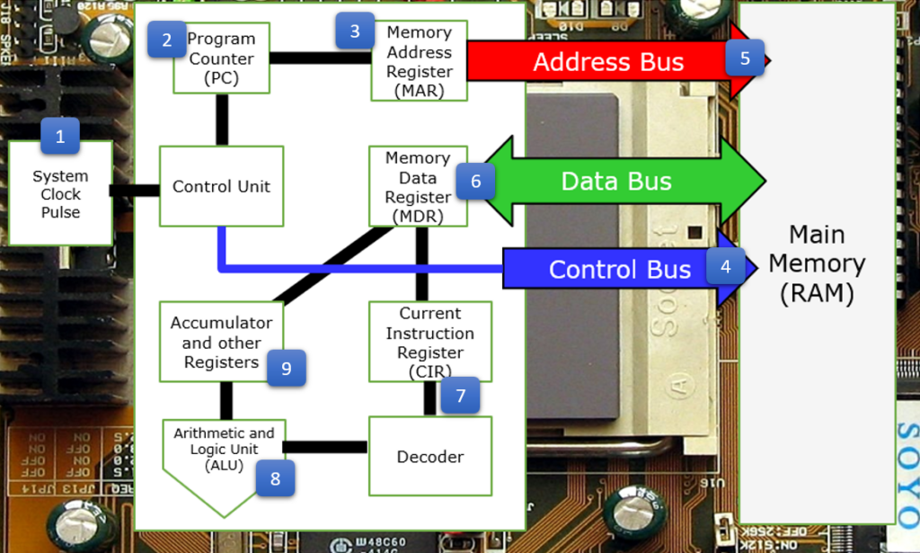
When memorising the Fetch, Decode, Execute cycle it can be really beneficial to think about the diagram above - we are travelling around the diagram in a clockwise direction from the System Clock / Control Unit. The detailed steps of the cycle are below and... yes, you do need to know them off the top of your head.
| Step Number | What happens |
| 1 | A clock pulse is generated, triggering the Control Unit to begin the next phase of the cycle |
| 2 | The Program Counter (PC) is incremented |
| 3 | The contents of the Program Counter is copied to the Memory Address Register (MAR) |
| 4 | A “read” signal is sent by the Control Unit, down the Control Bus, to the memory controller |
| 5 | The address is sent down the Address Bus and the contents of the relevant memory location is read |
| 6 | The data is sent from memory, down the Data Bus to the Memory Data Register (MDR) |
| 7 | The Memory Data Register is copied to the Current Instruction Register (CIR) where it is split into operator and operand |
| 8 | The instruction in the CIR is decoded and then executed in the Arithmetic Logic Unit (ALU) |
| 9 | The results of the instruction execution are placed in the Accumulator |
In reality, this isn't the end of the cycle, but that's because "step 10" would depend on what the next instruction to be executed was. There are two options - the next instruction will work on the data stored in the Accumulator or the data will be sent to the memory data register in order to be sent back to main memory for later use. Don't worry about any of this, you won't need to know it for the exam, but it's nice to know for completeness.
